Intelligent Robotic Tangram Puzzle Solver 智能机器人七巧板求解器
Computer vision and machine learning for autonomous puzzle solving 计算机视觉和机器学习实现自主谜题求解
C++, Python, ROS2, YOLO, Convolutional Autoencoder, Sematic Segmentation, Computer Vision, Machine Learning, Robot Kinematics
Source Code: The source code for this project can be found here: GitHub
Objective
This project’s primary objective is the design and implementation of a robotic system engineered to autonomously solve tangram puzzles as specified by a user. The inherent NP-hard nature of tangram puzzles presents a considerable challenge for automated solutions. This work focuses on developing a system that integrates sophisticated algorithms for perception, planning, and robotic control, thereby enabling the precise assembly of tangram components into a target configuration. Through the application of advanced techniques in computer vision, machine learning, artificial intelligence, and robotic manipulation, this project endeavors to showcase the capacity of robotic systems to address complex tasks with high levels of precision and operational efficiency.
Hardware Setup
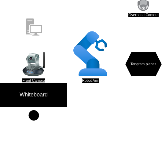
The hardware configuration, depicted in the accompanying figure, comprises a robotic arm and two cameras: an overhead camera and a front-facing camera.
- Robot Arm: Utilized for manipulating tangram pieces during the puzzle-solving process.
- Overhead Camera: Employed for detecting the poses of the individual tangram pieces.
- Front Camera: Tasked with detecting the outline of the target puzzle.
Hand-Eye Calibration
The hand-eye calibration procedure involves positioning an AprilTag within the robot arm’s operational workspace, as illustrated below. The calibration mechanism aligns the robot arm’s end-effector with the AprilTag. Subsequent calculation of the homogeneous transformation matrix yields the spatial relationship between the robot frame and the camera frame.
Denoting $ r $ as the robot frame, $ c $ as the camera frame, and $ t $ as the tag frame, the transformation $ T_{rc} $ from the robot frame to the camera frame is determined by the following equation:
\[\begin{aligned} T_{rc} &= T_{rt} \cdot T_{tc} \\ &= T_{rt} \cdot T_{ct}^{-1} \end{aligned}\]Here:
- $ T_{rt} $: Transformation from the robot frame to the tag frame.
- $ T_{tc} $: Transformation from the tag frame to the camera frame.
This method ensures accurate calibration of the system, enabling precise spatial localization and coordination between the robot arm and the camera.
System Workflow
The complete tangram solving system integrates multiple subsystems for perception, planning, and manipulation.
flowchart TD
    START([System Start]) --> CALIB[Hand-Eye Calibration]
    CALIB --> DETECT_PUZZLE[Detect Target Puzzle<br/>YOLOv11]

    DETECT_PUZZLE --> SOLVE[Solve Puzzle<br/>CAE Model]
    SOLVE --> SEGMENT_TARGET[Segment & Extract<br/>Target Poses]

    SEGMENT_TARGET --> DETECT_PIECES[Detect Current Pieces<br/>Semantic Segmentation]
    DETECT_PIECES --> MATCH[Match Pieces to Targets]

    MATCH --> PLAN[Generate Pick-Place Actions]

    PLAN --> LOOP{All Pieces<br/>Placed?}
    LOOP -->|No| PICK[Pick Piece i]
    PICK --> MOVE[Move to Target]
    MOVE --> PLACE[Place Piece]
    PLACE --> UPDATE[Update State]
    UPDATE --> LOOP

    LOOP -->|Yes| COMPLETE([Puzzle Complete])

    style START fill:#d4edda
    style CALIB fill:#fff4e1
    style SOLVE fill:#e1f5ff
    style COMPLETE fill:#d4edda
Software Architecture
The software architecture for this project is implemented using ROS2, comprising eight interconnected packages. Each package fulfills a specific role in enabling the robotic system to autonomously solve tangram puzzles. The overall system relies on these packages for functionalities ranging from hardware interfacing and image processing to motion planning and execution.
graph TB
    subgraph Vision["Computer Vision Pipeline"]
        IMG_SEG[image_segmentation<br/>ML Models]
        PIECE_DET[piece_detection<br/>Pose Estimation]
        PUZZLE_SOLV[puzzle_solver<br/>CAE + Planning]
    end

    subgraph Control["Robot Control"]
        MAXARM[maxarm_control<br/>Low-level Control]
        TANGRAM_BOT[tangram_bot<br/>Action Orchestration]
    end

    subgraph Utilities["Support Systems"]
        CALIB[hand_eye_calibration<br/>TF Calibration]
        MSGS[tangram_msgs<br/>Message Definitions]
        UTILS[tangram_utils<br/>Geometry Functions]
    end

    IMG_SEG --> PIECE_DET
    IMG_SEG --> PUZZLE_SOLV
    PIECE_DET --> TANGRAM_BOT
    PUZZLE_SOLV --> TANGRAM_BOT
    TANGRAM_BOT --> MAXARM

    CALIB --> PIECE_DET
    CALIB --> PUZZLE_SOLV
    MSGS --> PIECE_DET
    MSGS --> PUZZLE_SOLV
    MSGS --> TANGRAM_BOT
    UTILS --> PIECE_DET
    UTILS --> PUZZLE_SOLV
    UTILS --> TANGRAM_BOT

    style IMG_SEG fill:#e1f5ff
    style MAXARM fill:#fff4e1
    style TANGRAM_BOT fill:#d4edda
ROS2 Packages
The core software is modularized into the following ROS2 packages:
hand_eye_calibration: Implements the necessary procedures for hand-eye calibration, which is crucial for determining the precise spatial relationship between the camera’s coordinate frame and the robot’s coordinate frame.image_segmentation: Contains and executes the computer vision models utilized in this project. Its primary function is to segment images based on pre-trained models, identifying relevant features such as tangram pieces or puzzle outlines.maxarm_control: Manages the low-level position control of the robot arm. This package ensures that the robot arm can move to desired positions and orientations with accuracy.piece_detection: Responsible for detecting the pose (both position and orientation) of all individual tangram pieces within the robot’s workspace. This information is vital for the subsequent planning and manipulation stages.puzzle_solver: Generates the target or goal pose for each tangram piece required to solve the given puzzle. This involves determining the final configuration of all pieces.tangram_bot: Orchestrates the overall robot behavior. It generates and executes the sequence of actions required to pick up individual tangram pieces and place them in their designated target poses, ultimately assembling the complete puzzle.tangram_msgs: Defines all custom message types and service interfaces used for Inter-Process Communication (IPC) between the various ROS2 nodes within the system. This ensures seamless data exchange and coordination among the different software modules.tangram_utils: Provides a library of utility functions specifically for tangram-related geometric calculations. These functions support operations such as pose transformations, shape analysis, and other mathematical computations necessary for the project.
Tangram Puzzle Detection
For puzzle detection, a YOLOv11 object detection model was trained to identify shapes drawn on a whiteboard. Upon successful detection, the system queries a database to retrieve the corresponding image. This selected shape image is subsequently input into the tangram puzzle-solving model for analysis and solution generation.
Tangram Puzzle Solver
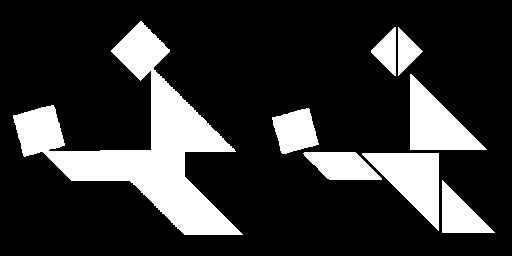
To address the complexities of solving tangram puzzles, this work draws upon methodologies presented in the paper Generative Approaches for Solving Tangram Puzzles. The referenced study introduces a Convolutional Autoencoder (CAE) architecture, specifically tailored for tangram puzzle segmentation.
The CAE system accepts a tangram puzzle image as input and produces a segmented representation of its constituent shapes as output. This process facilitates a sequential approach to puzzle resolution. The accompanying figure illustrates this input-output relationship, highlighting the CAE’s proficiency in decomposing the puzzle.
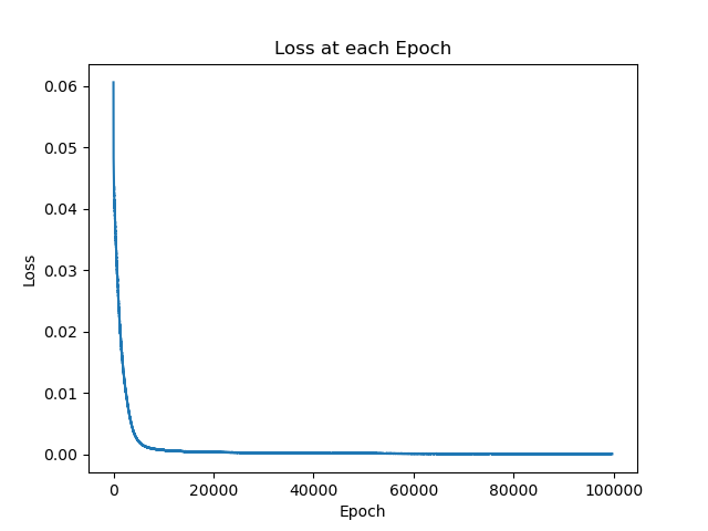
The training loss over epochs is depicted in the figure below, demonstrating the model’s convergence during training:
Target Pose Detection
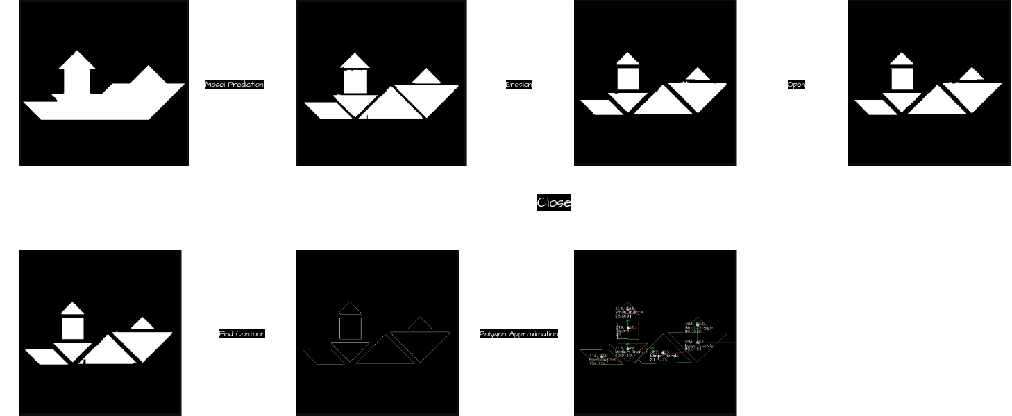
The methodology for determining the configuration of each tangram piece within the robot’s reference frame is depicted in the diagram above. This workflow ensures the accurate identification and localization of each piece, crucial for effective robotic manipulation. The sequential steps are as follows:
- Model Prediction (CAE): The input puzzle image is processed by a trained Convolutional Autoencoder (CAE) to segment the tangram puzzle into its individual components and identify their respective target configurations.
- Erosion: The boundaries of each segmented mask undergo an erosion operation to prevent the erroneous fusion of adjacent tangram pieces.
- Opening: Morphological opening is applied to eliminate extraneous white noise from the black background, thereby ensuring a clean segmentation of the puzzle pieces.
- Closing: Morphological closing is utilized to remove black noise artifacts within the tangram pieces, preserving their geometric integrity.
- Contour Detection: The
Cannyedge-detection algorithm is employed to accurately locate the contours of each tangram piece, effectively isolating their perimeters. - Polygon Approximation: The detected contours are approximated to the nearest polygonal representation, enabling the precise determination of each tangram piece’s shape and orientation.
This comprehensive approach leverages the CAE model in conjunction with robust image processing techniques to ensure that tangram pieces are accurately configured within the robot’s operational frame, thereby facilitating precise and efficient robotic operations.
Tangram Piece Detection
To enable the robot arm to accurately pick up tangram pieces, semantic segmentation was implemented in combination with morphological transformations. This approach effectively identifies the shape and pose of each tangram piece, ensuring precise localization for robotic manipulation.
Tangram Pose Detection
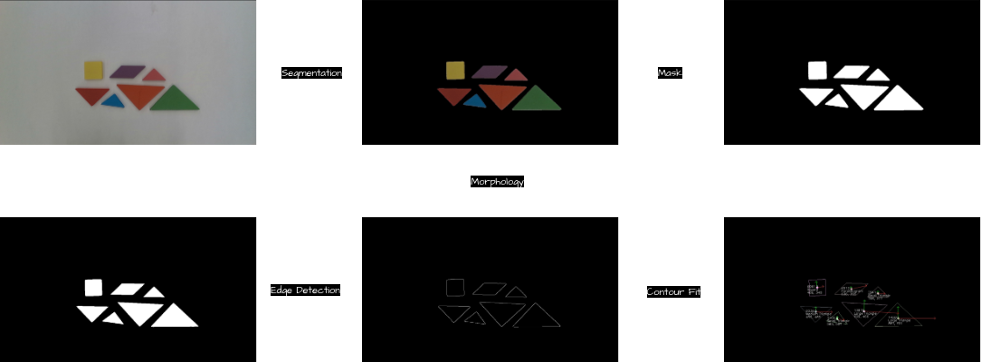
As illustrated in the figure above, the workflow for detecting the pose of tangram pieces includes the following steps:
- Semantic Segmentation: Segment the input image to identify individual tangram pieces.
- Mask Generation: Generate a mask from the segmented image to isolate each tangram piece.
- Edge Detection: Apply edge-detection algorithms to identify the contours of the tangram pieces from the masked image.
- Contour Analysis: Analyze each detected contour to determine its centroid, shape, and orientation.
- Deprojection: Transform the $ x, y $ pixel coordinates into $ x, y, z $ Cartesian coordinates within the camera frame, enabling precise 3D localization of the tangram pieces.
Frame Transformation
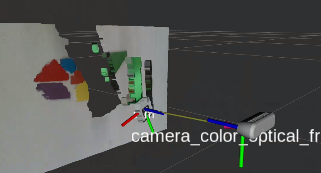
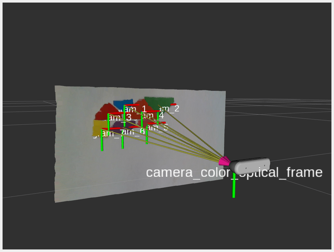
From the Hand-eye Calibration step, the transformation matrix $ T_{rc} $ (robot frame to camera frame) was obtained. Using this transformation, the position of each tangram piece in the camera frame ($ \vec{p}_c $) can be converted to the corresponding position in the robot frame ($ \vec{p}_r $).
The transformation is computed as follows:
\[\vec{p}_r = T_{rc} \times \vec{p}_c\]This calculation enables accurate localization of tangram pieces in the robot’s coordinate frame, ensuring precise robotic manipulation during the assembly process.
The resulting detected position of each tangram piece in the camera frame is shown in the figure below:
Robot Action Planner
Upon determination of the current poses of the tangram pieces and their respective target positions, a sequence of robotic actions was developed to orchestrate the assembly process.
sequenceDiagram
    participant Planner as Action Planner
    participant IK as Inverse Kinematics
    participant Arm as Robot Arm
    participant Gripper as End Effector

    Note over Planner: For each tangram piece

    Planner->>IK: Compute approach trajectory
    IK->>Arm: Send joint commands
    Arm->>Gripper: Move to pre-grasp pose

    Planner->>IK: Compute grasp pose
    IK->>Arm: Execute grasp motion
    Arm->>Gripper: Align with piece

    Gripper->>Gripper: Close gripper (grasp)

    Planner->>IK: Compute lift trajectory
    IK->>Arm: Lift piece vertically
    Arm->>Gripper: Raise above workspace

    Planner->>IK: Compute placement trajectory
    IK->>Arm: Move to target location
    Arm->>Gripper: Position at target pose

    Planner->>IK: Lower to placement height
    IK->>Arm: Execute placement
    Gripper->>Gripper: Open gripper (release)

    Arm->>Arm: Retract to safe position

    Note over Planner: Repeat for next piece
The workflow encompasses the following stages:
- Pose Mapping: Leveraging the computed current and target poses, the system calculates an optimal path for each tangram piece.
- Pick-and-Place Strategy: The robotic arm is programmed to execute precise pick-and-place maneuvers, which include:
- Navigating to the detected position of each tangram piece.
- Adjusting the gripper mechanism for secure acquisition, based on the specific shape and orientation of the piece.
- Lifting the piece while avoiding disturbance to adjacent components.
- Path Planning: Collision-free trajectories are generated to ensure smooth transit from the current pose to the designated target pose.
- Placement Accuracy: Upon reaching the target position, the robot arm adjusts the piece’s orientation to match the required alignment and executes a gentle placement.
This systematic process enables the robot to sequentially pick up each tangram piece and assemble them into the final puzzle configuration with a high degree of precision and operational efficiency.
Robot Controller
The robot arm, actuated by four servo motors, is controlled through precise angular adjustments of each motor. To achieve accurate movement to specified $x, y, z$ Cartesian coordinates, forward and inverse kinematics were implemented. This ensures precise motion control and positioning of the robot arm within its Cartesian workspace.
Kinematics
To develop the forward and inverse kinematics for the robotic arm, principles from the textbook Modern Robotics were applied. This reference guided the modeling and implementation of the kinematics algorithms essential for precise control of the robot arm’s motion.
Robot Modeling
As depicted in the accompanying figure, the robot arm is a 4-DOF (Degrees of Freedom) system incorporating a 4-bar linkage mechanism. This design ensures the end-effector consistently maintains a downward orientation during its operation.
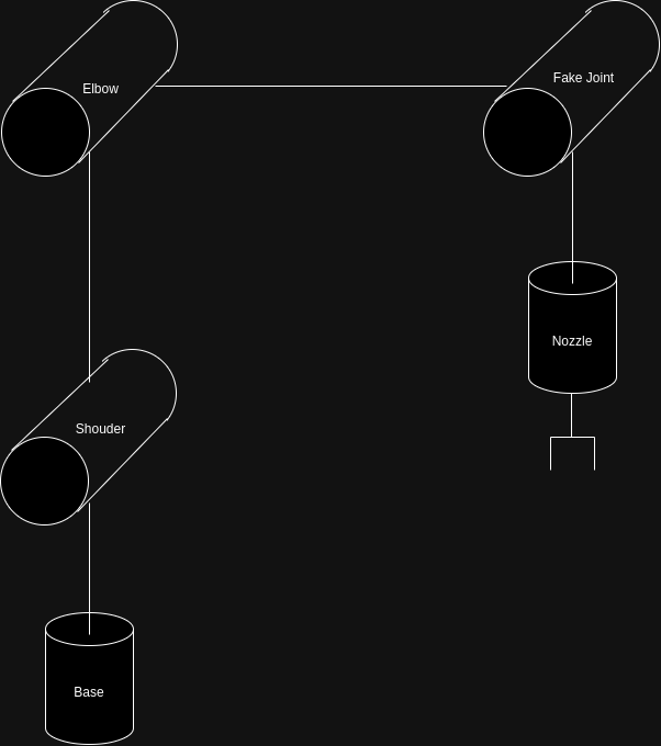
To accurately model the kinematics of the robot arm, inclusive of its 4-bar linkage, a virtual joint was introduced (as illustrated in the figure). This adaptation facilitates a precise representation and computation of the robot’s motion dynamics.
The home configuration can be denoted as
\[M = \begin{bmatrix} 1 & 0 & 0 & L_3 \\ 0 & -1 & 0 & 0 \\ 0 & 0 & -1 & L_1 + L_2 - L_4 \\ 0 & 0 & 0 & 1 \end{bmatrix}\]And the ${\cal S}{list}$ and ${\cal B}{list}$ can be represented as
\[\begin{align*} S_{list} &= \begin{bmatrix} 0 & 1 & 1 & 1 & 0 \\ 0 & 0 & 0 & 0 & 0 \\ 1 & 0 & 0 & 0 & -1 \\ 0 & 0 & 0 & 0 & L_3\\ 0 & L_1 & L_1 + L_2 & L_1 + L_2 & 0\\ 0 & 0 & 0 & -L_3 & 0 \end{bmatrix} \\ B_{list} &= \begin{bmatrix} 0 & 0 & 0 & 0 & 0 \\ 0 & 1 & 1 & 1 & 0 \\ -1 & 0 & 0 & 0 & 1 \\ 0 & L_4 - L_2 & 0 & L_4 & 0 \\ 0 & 0 & 0 & 0 & 0\\ 0 & -L_3 & -L_3 & 0 & 0 \end{bmatrix} \\ \end{align*}\]Forward and Inverse Kinematics
After finishing modeling the robot, we could apply the equations described in book Modern Robotics for calculating the forward and inverse kinematics \(T_{sb}(\theta) = Me^{[{\cal B_1}]\theta_1}e^{[{\cal B_2}]\theta_2}e^{[{\cal B_3}]\theta_3}e^{[{\cal B_4}]\theta_4}e^{[{\cal B_5}]\theta_5}\)
Result
The successfully assembled tangram puzzle is presented in the figure below, demonstrating the robotic system’s capability to complete the complex task. This outcome highlights the effective integration of advanced algorithms for perception, planning, and manipulation in achieving precise puzzle assembly.
Future Work
Several components within the project have been identified for potential enhancement in future iterations.
- Robot Control: Due to inherent hardware limitations, the precision of the robot actuators is insufficient for consistently accurate grasping of all tangram pieces. Future work could involve the implementation of a closed-loop control system. This system would utilize an AprilTag mounted on the robot arm to provide real-time feedback, thereby improving grasp accuracy and overall manipulation reliability.
References:
-
Fernanda Miyuki Yamada, Harlen Costa Batagelo, João Paulo Gois, and H. Takahashi, “Generative approaches for solving tangram puzzles,” Discover Artificial Intelligence, vol. 4, no. 1, Feb. 2024, doi: https://doi.org/10.1007/s44163-024-00107-6.
-
K. M. Lynch and F. C. Park, Modern robotics : mechanics, planning, and control. Cambridge: University Press, 2017.
C++, Python, ROS2, YOLO, 卷积自编码器, 语义分割, 计算机视觉, 机器学习, 机器人运动学
源代码: 该项目的源代码可以在这里找到: GitHub
目标
该项目的主要目标是设计和实现一个能够自主求解用户指定七巧板谜题的机器人系统。七巧板谜题固有的 NP-hard 特性为自动化解决方案带来了相当大的挑战。这项工作专注于开发一个集成感知、规划和机器人控制的复杂算法系统,从而能够将七巧板组件精确组装成目标配置。通过应用计算机视觉、机器学习、人工智能和机器人操作方面的先进技术,该项目致力于展示机器人系统以高精度和操作效率处理复杂任务的能力。
硬件设置
硬件配置包括一个机械臂和两个摄像头:一个俯视摄像头和一个前置摄像头。
- 机械臂:用于在求解过程中操作七巧板块。
- 俯视摄像头:用于检测各个七巧板块的位姿。
- 前置摄像头:用于检测目标谜题的轮廓。
软件架构
该项目的软件架构使用 ROS2 实现,包含八个相互连接的软件包。
ROS2 软件包
核心软件被模块化为以下 ROS2 软件包:
hand_eye_calibration: 实现手眼标定所需的程序image_segmentation: 包含并执行本项目中使用的计算机视觉模型maxarm_control: 管理机械臂的底层位置控制piece_detection: 负责检测工作空间内所有单个七巧板块的位姿puzzle_solver: 生成求解给定谜题所需的每个七巧板块的目标位姿tangram_bot: 协调整体机器人行为tangram_msgs: 定义用于节点间进程间通信的所有自定义消息类型和服务接口tangram_utils: 提供专门用于七巧板相关几何计算的实用函数库
结果
成功组装的七巧板谜题展示在下图中,证明了机器人系统完成复杂任务的能力。
参考文献
-
Fernanda Miyuki Yamada, Harlen Costa Batagelo, João Paulo Gois, and H. Takahashi, “Generative approaches for solving tangram puzzles,” Discover Artificial Intelligence, vol. 4, no. 1, Feb. 2024.
-
K. M. Lynch and F. C. Park, Modern robotics : mechanics, planning, and control. Cambridge: University Press, 2017.